VTK 技术总结(二)多边形 Outline 和 Feature Line 创建
多边形Outline和 Feature Line 创建
根据上一文章中,我们成功创建了一个正方形在创建的VTK视图中。但是在未来的计划中,我们还要想体现更为复杂的模型。而模型是由不同的点,线,面组成的。相比较ABAQUS中的Mesh来说,这些点线面(Feature)其实就是node, face element, body element。
那么如何在VTK的视图中展示这些特征呢?下面我们以一个简单的例子来说明:
1 | # vtk DataFile Version 1.0 |
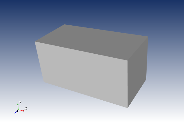
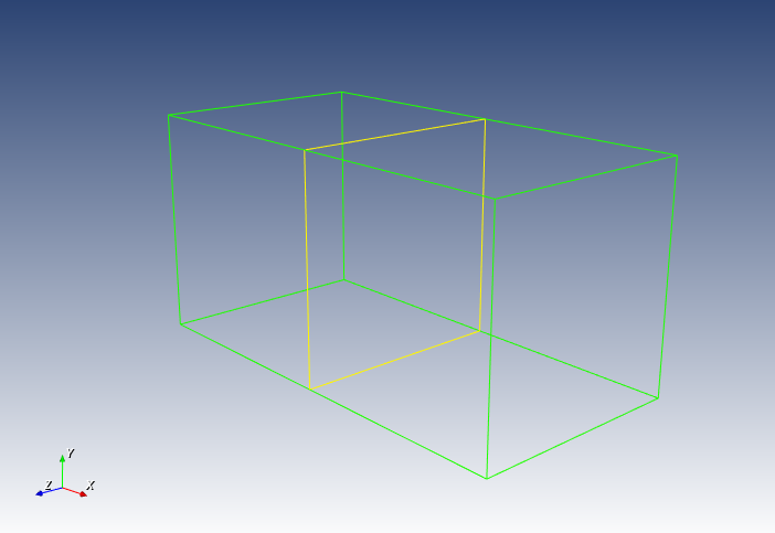
这个文件能够显示一个含有两个正方体的模型组成的长方体。如下图所示
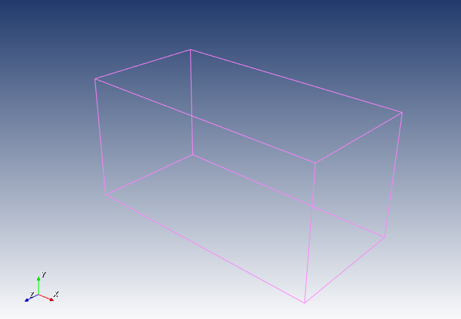
显示模型边线
这里要使用vtkOutlineFilter()来实现这个功能:
1 | # Outline |
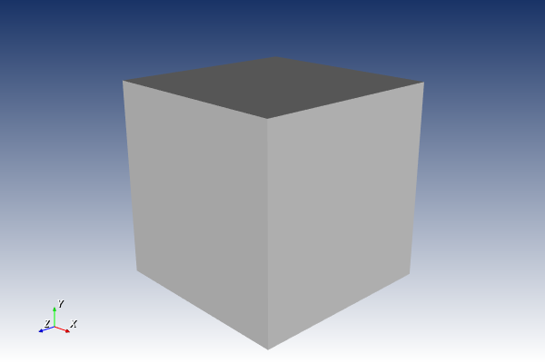
将上述代码添加到该系列文档中的第一个文章中的代码中。则可显示出模型的边线,如图,这里把模型本身隐藏了
这里我们可以看出来,这个功能并不能显示出内部面的框线。如果想要实现显示内部框线,那我们需要vtkFeatureEdges这个功能。代码如下:
1 | featureEdges = vtk.vtkFeatureEdges() |
选择打开FeatureEdgesOn()
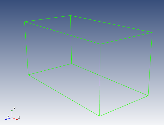
可以看出来Outline 和 Feature Edges的显示是一样的。
我们再打开ManifoldEdgesOn,其中 Manifold edges 意思为交叠边,就是模型内部重复使用的边。
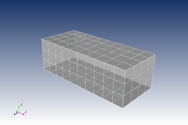
我们打开FeatureEdges和NonManifoldEdges,就可以得到类似ABAQUS中隐藏实体网格一样的网格边线了。
本博客所有文章除特别声明外,均采用 CC BY-NC-SA 4.0 许可协议。转载请注明来源 孙国文的博客 - Guowen Sun's Blog!
相关推荐
2025-01-13
VTK 技术总结 番外篇 (三)Inp2VTK based on C3D8R
INP和VTK 文件其实当我们了解了一些基本的VTK 文件格式,例如如何编写含有unstructured grid信息的.vtk文件,之后,我们就可以自己根据构思来去设计一些体素模型。然而,对于复杂模型来说,或者含有大量几何信息的模型来说,凭脑子来一点点的设计和堆积一个个CELL到我们的文件数据集中,肯定是不可能的。毕竟人脑能够构思框架和使用,但是机脑才是那个负责重复劳动的东西。 对于熟悉ABAQUS有限元的人来说,INP文件是最常接触的文件,它里面涵盖了有限元分析所需求的各种模型信息以及边界条件。ABAQUS的后处理功能虽然能够提供我们必要的一些信息,但是如果我们想了解有限元分析结果的数据结构,判断其结果准确性等等,我们就需要一些更强大的图形展示窗口,比如PARAVIEW。而且,我们还能更方便的基于从ABAQUS 中获得的结果文件,做进一步的分析,比如,Multiscale modelling 多尺度分析。但是在这里就不深入讲解了。 综上,INP文件转化为VTK文件,然后显示到PARAVIEW,或者我们自己编写的基于VTK 的图形窗口中,就显得很必要了。 INP...
2025-01-13
VTK 技术总结(一)多边形创建
多边形创建传统VTK 文件包含五个部分: 文件版本和标识符。这一部分包含# vtk DataFileVersion x.x,除了版本号x.x之外,该行必须与显示的完全相同。 标题。标题由以行尾字符\n终止的字符组成。最大为256个字符,可用于描述数据并包括任何其它相关信息。 文件格式。文件格式描述文件的类型,可以是ASCII 或者二进制。在此行上,必须出现单个单词ASCII或者BINARY 数据集结构。几何部分描述了数据集的几何和拓扑。这部分以包含关键字DATASET 的行开头,后跟描述数据集类型的关键字。然后根据数据集的类型,其他关键字/数据组合将定义实际数据。 数据集属性。以关键字POINT_DATA或CELL_DATA开头,后跟一个整数,分别指定点或单元的数量。(先出现POINT_DATA还是CELL_DATA都没关系)。然后,其他关键字/数据组合定义实际的数据集属性值(即标量,向量,张量,法线,纹理坐标或字段数据)。 12345678910111213# vtk DataFile Version 1.0Vibrational modes...
2025-01-13
VTK 技术总结(三)显示unstructured grid 的网格线
非结构化Grid 的网格线之前我们说过如何查看两个多面体内部的Feature Lines 和外部的 Outline。然而那种方法只适用于Polygonal data,对于Unstructure Grid 并不适用。所以如果我们想要将Unstructured Grid显示出来,那么就需要vtkGeometryFilter这个功能。详情请看下图: Putanowicz and Magoules simplified the visualization process of unstructured grids with VTK [1]. The figure shown above clearly displayed how the outline grid can be presented by the VTK reader. 总体的实现过程可查看如下代码: 1234567891011121314151617181920212223242526272829def file_open(self, path): vtkReader =...
2025-01-13
VTK 技术总结 番外篇 (一)VTK文件格式以及数据集
文件格式文件内容简介第一行是数据版本声明,说明文件版本。 第二行是自己定义的一个标题,最多256个字符,以回车符\n结束。 第三行是文件格式生命,由两个选择,ACSII或者二进制BINARY。 123# vtk DataFile Version 1.0Model_1ASCII 之后就是最重要的数据集了。是以DATASET type 格式来体现的。其中type 可以是 STRUCTURED_POINTS STRUCTURED_GRID UNSTRUCTURED_GRID POLYDATA RECTILINEAR_GRID FIELD 如果使用UNSTRCTURED_GRID: ‘The unstructured grid dataset consists of arbitrary combinations of any possible cell type. Unstructured grids are defined by points, cells, and cell types. The CELLS keyword requires two parameters:...
2025-01-13
VTK 技术总结 番外篇 (二)VTK 视图化过程
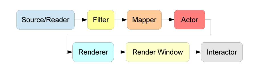
Visualization pipeline这篇文章的大部分内容来自于:http://www.cb.uu.se/~aht/Vis2014/lecture2.pdf 。作者是Johan Nysjö。 VTK视图化的过程可以体现在Figure 1. 其中source 是来源于 VTK 内部的模型,包含了一些简单的正方体,棱柱,圆等等。Reader主要是用来读取外部文件的模型信息。 Filter 的主要作用是传递和修改输入的信息。它可以被用来: Select data of a particular size, strength, intensity, etc. Process 2D/3D images or polygon meshes/ Generate geometric objects from data. Mapper 是用来将数据投影到图形基元(点线面)以至于这些数据可以被renderer呈现出来。更多情况下,我们使用的是vtkPolyDataMapper。 Actors...
2025-01-13
使用Python+SolidWorks自动化创建复合材料元胞 (一)
复合材料元胞复合材料元胞(Unit Cell)是复合材料层合板中的代表性单元,其在层合板中具有周期性,也被称为Representative Unit Cell (RUC)。RUC 是中尺度模型(Mesoscale model),同时也有RVE(Representative Volume Element),是微尺度模型(Microscale level)。Unit cell (UC)经常被用来代替整个复合材料平板模拟复合材料在不同工况下的力学性能。因此能够准确建立元胞模型并用于ABAQUS等有限元的模拟中,就显得尤为重要。 但是通常通过CAD软件,如SolidWorks (SW),建立复合材料元胞是一个复杂且费时的过程。我们不仅需要了解编织复合材料预制件的各种制造参数,而且还需要通过3D绘图软件成功建立出不同样式的元胞。这样就会造成大量的时间和经历的浪费。 现在已经有很多的开源软件可以用来制造中尺度的元胞模型,如诺丁汉大学的开业软件:TexGen (中尺度模型的建立),Prof Shuguang Li,Laurent Jeanmeure 和 Qing...